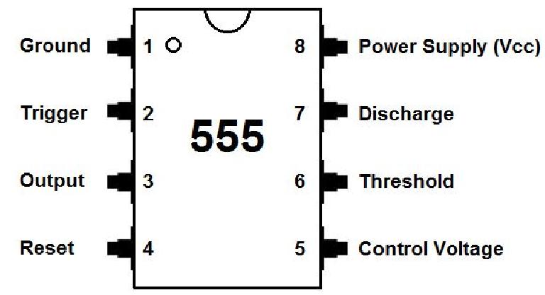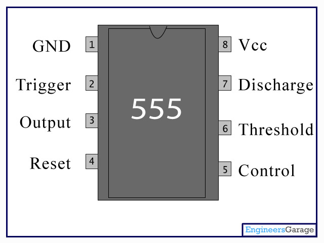

When not in use it is recommended that this input be connected to circuit ground via a 0.01uF capacitor. This enables you to vary the length of the output pulse in monostable mode or the output frequency in astable mode. You can vary it from 45% to 90% of the supply voltage. You can control the threshold voltage (pin 6) through the control input (which is internally set to 2/3 the supply voltage).

This input should remain connected to Vcc when not used.

The output can source or sink up to 200 mA (maximum depends on supply voltage).Ī low voltage (less than 0.7V) applied to the reset pin will cause the output (pin 3) to go low. For example, if the supply voltage is 5V output high voltage will be 3.3 volts. In output high state the voltage will be 1.7V lower than the supply voltage. In output low state the voltage will be close to 0V. The output will remain high until a high voltage is applied to the Threshold input (pin 6). Pin 1 – Ground (GND) This pin is connected to circuit ground.Ī low voltage (less than 1/3 the supply voltage) applied momentarily to the Trigger input causes the output (pin 3) to go high. Arduino Tutorial Online Courses Video Training.Arduino Nano Projects List in PDF offline downloadable.Android based arduino Projects List Download PDF.esp8266 arduino projects list in pdf offline downloadable.Arduino Proteus Projects List for Download.Arduino UNO Projects List in PDF offline downloadable.

Arduino Mega 2560 projects list in PDF offline downloadable.Arduino Complete Projects List PDF Downloadable.Huge List of tutorials & Components based resources.Plug in some headphones and if you can hear the tick tock of the metronome then you’re doneħ. The last thing to do is to test to make sure the audio output works. If everything is working as it should – congrats, you have pretty much finished. If not, check over your connections to make sure you didn’t forget anything and nothing is short circuited.Ħ. Add the battery and check to make sure the circuit is working. Make sure you get the polarity right by carefully checking the schematicĥ. Attach the 2 wires to the audio output jackĤ. Solder the 2 wires to the pot from the circuit.ģ. I usually solder the positive to the switch so connect the positive from the battery and the wire connected to positive from the circuit to the switchĢ. It’s really hard to take images of this step so I really just have a few finished ones to show you want it looks likeġ. This is the final step where you get to see whether the circuit will work first go or if you have to go over it and check to see if there are any short circuits or parts in the wrong place. It’s now time to solder that lot of spaghetti to the auxiliary parts and LED’s.


 0 kommentar(er)
